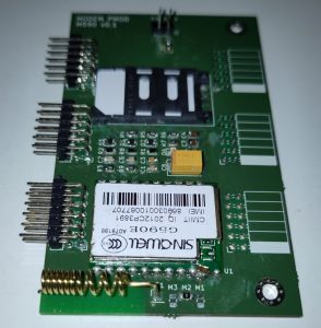
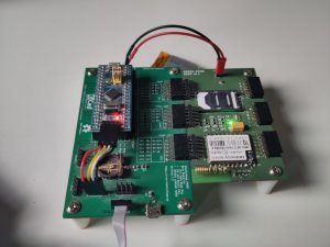
A while ago I wrote about GPRS Modules. The Neoway M590E kits, which came in 2018 for merely 89 cents from AliExpress. Those days are over, these days they come over for 3 euro something (including shipping) even though they become less and less useful as the 2G shutdown comes nearer and nearer. I want to do something with those modules before that day comes. As I’ve pointed out in the previous article, the supplied PCB is a piece of crap, so I’ve decided to make my own.
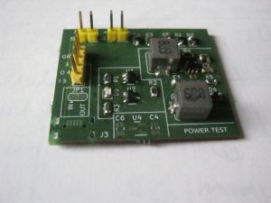
 In this first revision I’ve connected the UART and SIM card as recommended in the manual. I have left the power supply circuitry and put a header for a 3.5…4.2 volt supply, eg. a LiPo battery, as my PMOD boards are supplied with 3.3 Volts. I have created an additional board with a DCDC converter for testing the power circuitry to be added in a next revision. I intend to add a a DCDC converter in SEPIC configuration, to allow generating a 4 Volt supply from either the 3.3 Volts supplied by the PMOD connector or an external 5 Volts supply (USB charger), and additionally be able to connect a battery. My initial plans were to include a LiPo charger as well, but I decided to leave that out for now due space restrictions.
 While feeding the DCDC converter from 5 Volts seems to be able to supply the module fine, when feeding it from 3.3 Volts, the modem brownouts. It seems I need to add a fat capacitor. I’ve put some electrolytic capacitor on a breadboard. It seems 1 mF wasn’t enough, but when adding a 2.2 mF capacitor the modem doesn’t brown out. That’s a lot of capacitance, huh. But well… let’s see if I can come up with a next revision that doesn’t require a battery hanging next to it. There is a LiPo charger present in this test board, but it seems I can’t get it to fit on the next revision.
But let’s have a look at this revision. Of course I’ve made some mistakes. I didn’t connect the power on signal. Fortunately a drop of solder can bridge the power on pin to the GND pin next to it. The power on pin permanently grounded is mentioned in the manual for situations where the module should always be on, so this is legal. Another issue requiring a little botch wire is the fact I didn’t route the GND for the LED. The light will remain off, but otherwise not critical.
Now, most of the kits I’ve got came with a Neoway branded module. But one of them came with a Sinowell branded module, model G590E. This happened to be the module that I’ve soldered to my first prototype. When I connected it up, it didn’t response to AT commands at 115k2 bitrate. I connected my logic probe to the UART lines, and discovered this module was operating at 38k4 instead. When connecting at that bitrate, the modem responds to AT commands properly. However, this modem is not running Neoway firmware, as such, the Neoway specific AT commands are not valid. While the module is still listed at Sinowell’s website, it only contains a (Chinese) datasheet but no documentation of the AT commands it supports.
When soldering this module on, I noticed there were JTAG pads underneath. At the time I didn’t pay much attention to that fact, as I figured that would have been used in production or so. However, when communicating with this module, it shows interesting responses.
ATI MTK2 MAUI.10A.W11.16.MP.V37 OK |
AT+CGMI +CGMI: MTK1 OK |
AT+CGMM +CGMM: MTK2 OK |
AT+CGMR +CGMR: MAUI.10A.W11.16.MP.V37, 2012/04/14 15:38 OK |
Googling those strings reveals MAUI ain’t a cat meowing in a foreign language, rather, it is some hacking tool “Maui META Tool” intended to “Repair IMEI Issues” for MediaTek based devices. It this device running some testing firmware from the developers of that tool? Was that JTAG port significant after all? What the hell is this module? Anyhow, I couldn’t figure out how to change the bitrate permanently, or any commands for an integrated IP stack. It seems the only use for this module at this time is to start a PPP session and run an IP stack myself (eg. LwIP)
 Therefore I desoldered the module from the crappy Chinese board and put it on my own board. At least I know that module doesn’t bring any surprises. As mentioned, I’m working on a next revision of the board. I finished routing it yesterday. I might order it already or have another look over it. Anyhow, that’s it for now. I might first look into the firmware side for a bit.